Understanding the differences between UL and IEC standards for transformers is crucial for ensuring compliance and safety in various regions. This article delves into the unique attributes that define Class 2, Class 3, Class I, Class II, and Class III transformers, providing answers to the following key questions:
- What are Class 2 and Class 3 transformers?
- How are Class 2 and Class 3 transformers categorized?
- What defines Class I, Class II and Class III transformers?
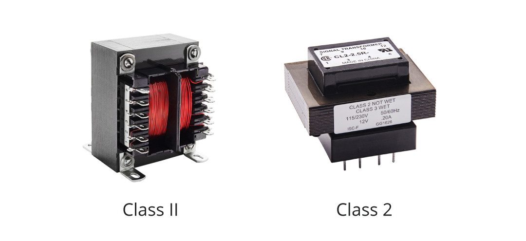
- How do Class 2 and Class II transformers differ?
- Are Class 2 and Class 3 transformers interchangeable with Class II and Class III?
UL/ANSI Type Class 2 and Class 3 Transformers
The National Electrical Code, American National Standards Institute, (ANSI) 70 / UL 5085-3, identifies the requirements for Class 2 and Class 3 transformers for use in Class 2 and Class 3 circuits respectively. For applications not related to the North American code-based standards, the Class 2 and Class 3 transformer have no home internationally.
Class 2 and Class 3 transformers are by definition, inherently limited, (self-limiting by impedance or PTC devices) or non-inherently limited, (relying on over current and or over temperature protection). The protection devices for Non-Inherently Limited transformers, (current fuses or circuit breakers), may not necessarily be inclusive to the transformer. These transformers have maximum open circuit output voltage and power limitations:
Power Limitations
- Class 2 Transformer: Maximum 30Vrms, (42.4V peak), maximum power is 100VA.
- Class 3 Transformer Inherently Limited: Greater than 30V but less than 100V.
- Class 3 Non-Inherently Limited Transformer: Maximum voltage is 150V.
Output Voltage Limitations
- Class 2 maximum output current is <8.0A, measured at 60 seconds under any load condition, including short circuit. However, when PTC components are utilized for protection, maximum current is measured at 5.0 seconds.
- Class 3 Non-inherently Limited: The output current is limited by the formula 1000/V.
- Class 3 Inherently Limited: The output current is limited by the formula 150/V.
Electrical Shock Hazard Protections
In addition to being limited in output current, output voltage and output power, Class 2 and Class 3 transformers must not cause a shock or fire hazard when exposed to continuous overload or short circuit conditions.
Class 2 transformers are often installed in low voltage control circuits; lighting fixtures, doorbells, alarm systems, HVAC systems, home appliances, video systems, garage door openers, furnace controls, or any place Class 2 circuits are required. Class 3 transformers are utilized in mid voltage control Class 3 circuits such as home theater, sound systems, public address, central alarm, and security systems. Class 3 circuits are less common than Class 2 circuits.
IEC Type Class I, II & III Transformers
Class I and Class II transformers do not have the same voltage and power limitations as their UL / ANSI type Class 2 and Class 3 counterparts and are not required to be inherently limited or non-inherently limited. However, Class III transformers do have output voltage limits.

Insulation Types and Grounding Requirements
Class I transformers are designed with two distinct layers of protection against electrical shock hazards. In addition to basic insulation, they feature an additional safety mechanism to provide earthing, (grounding) of accessible conductive parts within the fixed wiring of the installation. This additional safety measure ensures that even if the basic insulation fails, the conductive parts cannot become live, as they are securely grounded or earth protected.
Class II transformers are designed and constructed to prevent electrical shock hazards by relying on double insulation or reinforced insulation (terms common to many IEC and EN standards, including IEC 60664, IEC 61140 and IEC 61558-1). Double Insulation is defined as insulation comprising basic insulation plus supplementary insulation. Reinforced Insulation is defined as a single insulation system applied to hazardous live parts, which provides a degree of protection against electric shock equivalent to double insulation. Class II transformers have no provision for grounding, protective earthing, or reliance upon installation conditions.
Class III transformers rely on output voltage levels at Safety Extra Low Voltage (SELV), in which voltages higher than SELV are not generated. The maximum voltage value in a SELV circuit is <50V AC, or 120V ripple-free DC.
Identifying Markings and Compliance
IEC type Class I, II and III transformers may be designed to offer short circuit proof and non-inherent short circuit proof features. If such features are designed in, the appropriate symbols are displayed on the marking label. The IEC test requirements to verify short circuit proof and non-inherent short circuit proof transformers differ from those tests for North American Class 2 and Class 3 transformers.
Markings for UL/ANSI Type Transformers
In addition to markings for input voltage and frequency, output voltage and current, all North American Class 2 and or Class 3 transformers include the marking; “Class 2” or “Class 3” respectively. In addition, Class 2 and Class 3 transformers having an open circuit output voltage exceeding 15Vrms or 21.2 peak are marked with the following: “Class 2 not wet” or “Class 3 wet”. This marking indicates that when wet contact is likely, Class 3 wiring methods in accordance with Article 725 of the National Electrical Code (NEC) are to be utilized. The NEC Article 725 and ANSI/NFPA 70 specify the requirements for Class 2 and Class 3 circuits that are defined as the: “wiring system between the power source and the appliance”.
Class 2 power circuits are limited and do not pose fire initiation risk while providing an acceptable level of protection from electrical shock. Class 3 circuits are limited in output power however, they can and do operate at higher voltage levels and, therefore, can present a shock hazard in locations where wet conditions are likely to occur. Class 2 and Class 3 transformers with multiple output windings that, when interconnected, exceed 30Vrms or 42.2V peak, must be marked with: “Warning: Risk of electrical shock or fire. Do not interconnect secondary windings.”
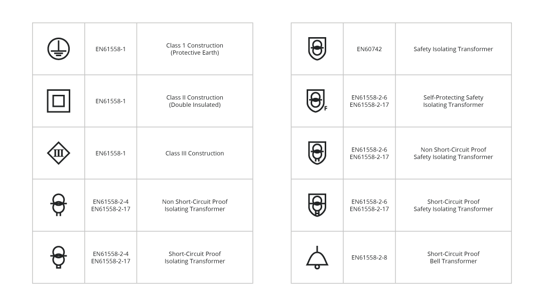
Markings for IEC Type Transformers
IEC Type Class I, Class II and Class III transformers are marked with details indicating the input voltage and frequency, output voltages and current ratings as well as symbols defining insulation type, and if applicable, protection means. Outlined in the table below are the symbols for Class I, Class II and Class III transformers, and symbols for transformers having various types of protection, i.e. Short Circuit Proof and Non-Short Circuit Proof.