

Choosing the right magnetics module for a LAN device is an important step toward ensuring signal integrity and meeting IEEE 802.3 and EMC compliance. Dealing with a potential EMI problem in the early stages of product design is a smart move that can give the LAN designers confidence and able to control product launch without delays or redesign due to EMI failure.
EMI Management
EMI noise is normally categorized as either emission or susceptibility. The parameters in LAN magnetics that contribute to reducing the noise of the system to the internal and external EMI are differential mode (DM) or common mode (CM) conversion. The CM-current noise can be propagated through the signal lines as either CM noise or DM noise. Depending on the CM-noise frequency of a system, Bel ICM products can target those frequencies to suppress the CM noise to an acceptable level. Since the higher the impedance, the lower the CM noise is. Bel engineers can review the preliminary EMI plots, electrostatic discharge (ESD) information, radiated immunity, or conducted immunity reports from the compliance lab to determine the right magnetic module to fix the system’s poor performance usually caused by layout issues, shielding, or system design to pass EMC compliance. Even with good layout practices the system may not meet EMC requirements if the designer selects low-quality components. The most important decision for LAN system designers is choosing the right LAN magnetic component with proper performance and good EMI suppression to address EMC problems as early in the design cycle as possible. If the system designer chooses the wrong magnetic module for their LAN devices, EMI issues may show up late in the design cycle, which can incur costly product redesign and product-launch postponement or delay.
LAN EMC Requirements
The impact of low-cost designs, including lower components count and increasing Physical Layer (PHY) transceiver sensitivity causes systems to be more susceptible to EMI and to fail to meet the compliance regulations for EMC. With the transmission speeds of 10 Gbps, a small amount of skew in the differential pair will cause mismatches of the rise and fall times, amplitude, and propagation delay between the differential pair, which are the sources of the CM- noise conversion on the differential signal lines. This causes the system to not meet EMC requirements. The internal structure of the magnetic ICM has to be well designed, from the internal PCB layout, internal shielding, and the toroid base structure to the windings and termination. The differential pair needs to be well balanced to ensure low CM conversion and high immunity to both external and internal noise sources.
EMC has two main requirements that every LAN system needs to satisfy: emission and susceptibility. Emission refers to the ability of the electronic device to be operated without interfering with other systems; susceptibility refers to the ability of the electronic device to continue to function properly within a specified electromagnetic environment. For the emission requirement—either radiated emission or conduct emission—before being released to the market, an LAN device must pass Federal Communications Commission (FCC) class A certification for enterprise-class equipment or FCC class B certification for residential electronic equipment. Susceptibility is the opposite of emission. It refers to how well a product functions when exposed to electromagnetic phenomena. The common forms of susceptibility are ESD, cable discharge event, radiated immunity, conducted immunity, and electrical fast transient/burst and surge.
ESD is a major test that measures the susceptibility of a system. When a device’s chassis is exposed to high-energy discharge from the ESD simulator (“ESD gun”) to test the immunity of the LAN system with either direct contact of +/– 8kV and air discharge +/– 15kV or other testing level, depending on the requirement, the high energy can couple into the signal lines and cause the device’s data link to drop and not be able to be recovered, which can cause a product to fail ESD requirements. In serious events, especially with high-speed, high-sensitive next generation PHY geometries, the discharge of high energy into the PHY can become destructive, which causes the system temporary or permanent damage. With careful structural design of the internal connector, Bel magnetic ICM has a layout such that the high energy will have the shortest path to the ground, meaning the least amount of high energy will be able to couple into the signal lines. In the event that the high-Common Mode energy gets coupled into the lines, the Bel ICM design will reduce the high energy to a sustainable level that the PHY can handle without any data corruption, providing high immunity to the system and allowing it to sustain the ESD event.
The ability of a LAN device to be immune to the radiated and conducted emissions is also important since the LAN device will encounter different types of EMI disturbances in the field. Radiated immunity and conducted immunity tests are designed to measure how well an electric device performs under stress conditions. Typical test levels can be 3V/m or 10V/m from 150 kHz to 80 MHz for conducted immunity and 80MHz up to 2.7GHz for radiated immunity depending on the requirements. Bel magnetic ICM can be effective to minimize the impact of the radiated electric fields that are often picked up from the cable or the PCB traces. The other tests to check the immunity of the system are electrical fast transient (EFT) and surge tests. The EFT immunity test is to measure how well the LAN device can still be function in the real world under disturbance conditions due to switching of inductive loads that may couple into the cable. The surge immunity is designed to check how well the LAN device can handle the power surges. There are many types of surges in the real world that may damage the LAN device. Bel magnetic ICM internal structure is designed to reduce the failures that can damage the system.
LAN Magnetics ICM
The magnetic module is a critical component in an LAN system. It is designed to meet signal-integrity requirements and to minimize undesirable EMI’s entry into the system, which causes the system to fail EMC requirements, especially a high-speed system with the fifth harmonic running at a tenth of a Gigahertz. Therefore, choosing the right magnetic manufacturer with experienced engineers to help a system pass the EMC regulation is a major decision for LAN system designers. Not all LAN magnetics are the same; using unqualified magnetics components may lead to issues, such as not meeting EMC requirements, delaying time to release a new product to the market, and higher cost. A qualified Bel magnetic ICM employing good design techniques will limit the amount of CM noise entering the system, so it can meet the EMC compliance requirements.
The Bel magnetic ICM is far more complex than it seems, with design tradeoffs between signal integrity and EMC that only technically competent LAN magnetic designers understand. They are able to help LAN system designers to choose the right magnetic ICM that can meet signal integrity and EMC requirements. The typical LAN magnetic ICM includes an isolation transformer to ensure the LAN devices meet the isolation requirements defined in the IEEE 802.3 standard. In addition to the isolation transformer, an LAN magnetic ICM also has a Common Mode Choke (CMC) in the series with the transformer to attenuate CM signal but allows desired differential signals to pass through. It may also contain termination resistors, decoupling capacitors, POE CMC for POE-enabled systems, or CM sense channel to reduce CM noise on the lines. Overall, the LAN magnetic ICM provides impedance matching, signal shaping and conditioning, high-voltage isolation, and CM-noise reduction. Ethernet uses UTP (Unshielded-Twisted-Pair) cable for data transmission, exposing it to the radiated emissions problem. The absence of a grounded shield means that the cable will radiate unless the differential signal is symmetrical and has a low level of Common Mode noise. The Common Mode noise that leaks through will show up on the signal lines, creating EMI problems.
Isolation Transformers
With proper internal printed circuit board (PCB) design and appropriate magnetic design to take care of common mode conversions, channel-to-channel crosstalk, and alien crosstalk, the Bel magnetic ICM will be a primary defender to protect the system against CM transient and provide the low-impedance path to ground to divert the high energy from ESD or CDE away from the signal path, preventing it from coupling into the lines and damaging the PHY. Using unqualified magnetics with poor internal design can aggravate the problem and lead to system failure.
Isolation transformers are used in an LAN magnetic module to provide voltage isolation between input and output of an LAN device, to realize the transformation of voltage or current, and to suppress the influence of CM disturbances. The ideal transformer will only transfer differential current and block all CM current. But a practical transformer will have a small capacitance that couples the primary and secondary windings. This small capacitance provides a low-impedance path for the unintentional CM current to transfer across the transformer, it can produce electrostatic coupling to other circuits which will affect the EMI performance of the channel.
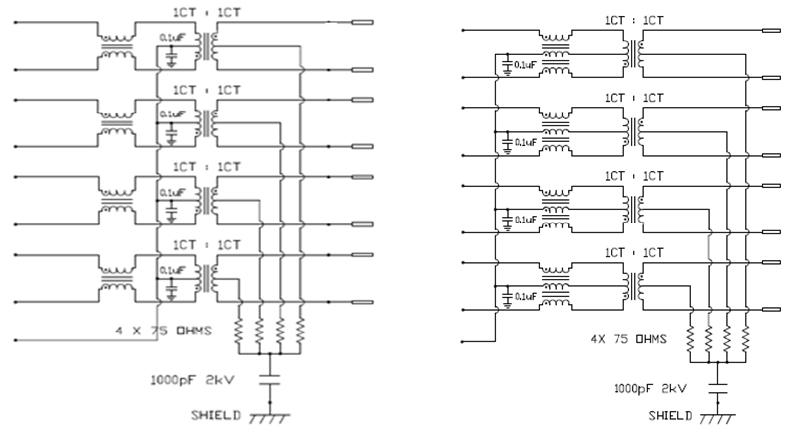
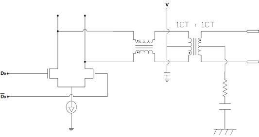
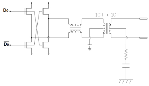
The transformer is a very important element in determining the LAN analog interface characteristics required by the IEEE 802.3 specification. The considerations for the transformer and associated input and output circuit design controlling the rise and fall time of the signal, maintaining waveform integrity and low percentage of droop for low frequencies, and designing for low inter-winding capacitance to achieve optimal CM rejection. The optimizing transformer leakage inductance and inter-winding capacitance are also used to control the frequency bandwidth and high or low rejection at desired frequencies. Figure 1 below are typical schematics of ICM module.
Common Mode Chokes
Another critical component in the Bel ICM is a common choke in every channel of the LAN circuit. At high frequencies, CM chokes are necessary for a system to meet EMC requirements. The CM choke displays high impedance for CM noise components, but low impedance against DM noise components. The most important factors that affect the emission and immunity of LAN devices are CM and CM noise. Using a UTP cable for LAN, each wire has the same average distance from sources of interference. This causes the interference to be predominantly CM with only a small residual amount remaining as CM interference. The CM currents are equal in magnitude but are directed in the same direction. These currents are not intentional, but they will be present in practical systems.
If the windings of a CMC are symmetric and all the flux remains in the core, then the impedance seen by the CM current will be zero, whereas impedance seen by the CM current will be high value. Thus, CMC can be effective in blocking undesirable CM noise but letting desirable differential signal through. In order to provide this impedance to CM noise, the wires must be wound around the core such that the fluxes due to the two CM currents add in the core, whereas the fluxes due to the two DM currents subtract in the core. The input and output of the windings should be positioned such that stray capacitance between them is minimal; otherwise, the stray capacitance would reduce the effectiveness of the CMC in blocking CM noise.
Below is the typical impedance curves of different CMC materials (Fig. 2). The impedance of a CMC is determined by the core material, size, and number of turns. Typically, CMC in the LAN magnetic ICM is using ferrite materials. The ferrites composed of iron oxide and one or more additional powdered metallic elements, such as nickel, zinc, or magnesium, can reduce the imposed EMI fields by suppressing electron movement; these ferrites are effective at suppressing both conducted and radiated emissions. The highest initial permeability material, such as manganese–zinc ferrite, is able to provide high impedance, but its permeability deteriorates more rapidly at higher frequencies than nickel–zinc. Therefore, depending on the frequency of interest, a proper selection of core material, size, and turn is necessary to suppress CM noise.
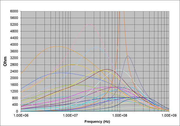
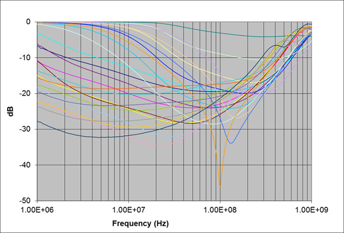
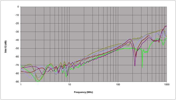
The higher the impedance, the better CM performance at that frequency. However, the CMC impedance will maximize at a specific frequency and lower at other frequencies. Furthermore, the CMC impedance will decrease at higher frequencies due to core saturation, so the number of turns and core material selection are important on the CMC design. The CM rejection of a CMC can be seen in Figure 3 or the CM to DM conversion of the whole module, magnetic ICM, can be seen in Figure 4.
PHY Transceiver Architectures
There are two main architectural designs for an Ethernet PHY transceiver. Such transceivers are either voltage mode line driver or current mode line driver PHYs, so the EMI problems are either related to current or voltage. Typically, the current mode PHY-related issues are associated with Differential Mode, and voltage mode PHY issues are associated with Common Mode. So the magnetics design for voltage mode-drive or current mode-drive PHY are different. With current mode line driver PHY, the current driver pulls a constant current from the voltage source V either 2.5V, 1.8V, or other voltage level, depending on the current required for the current mode line driver.
If using conventional CMC with two-wires winding through the toroid core, the constant current flows through the two-wire CMC either on a single winding or both windings based on either switch or both switches from the current driver being on. In all three stages, the current flows through CMC in the same direction, so there will not be any flux cancellation in the core. Without the flux cancellation in the core, the CMC interferes with the change of current, causing unintended signal distortion. Each Ethernet port has four channels and with multiport Integrated Circuit Module (ICM)—such as 2x4 or 2x6 ICM—the signal distortion can create further problems. To counter these problems, Bel engineers have designed three-wires winding CMC. This is proprietary and patented by Bel. With three-wires winding CMC, the transient current flows through the middle winding of the CMC, which is also the center tap of the transformer. This current is equal and out of phase with the currents flowing through the outer windings of the CMC. Therefore, the flux will be cancelled, which results in the net zero flux in the core, and the CM noise can flow through this low-impedance path to ground so the signal will not be distorted.
Current mode line driver PHY has more power dissipation than voltage mode line drivers. Therefore, for most of new PHYs, voltage mode line driver is the first choice. However, current mode line driver PHY (Figure 5) architectural design is often used by LAN PHY manufacturers due to its simpler design and lower cost. The voltage drive PHY uses the available 3.3V power supplies in its switch design; therefore, there is no need for a separate voltage source that connects to the transformer’s center tap. Without the pulled-down current through the center tap, two-wire CMC works well with voltage mode line driver to provide high impedance, limiting CM noise. However, a noisy board may inject ground noise into the system through the center tap of the transformer; Bel’s proprietary patented three-wire CMC design will filter the ground noise from the system board.
Autotransformers
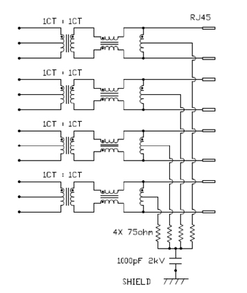
Another component that may be present in the LAN magnetic is an autotransformer. The autotransformer will act as high-value impedance to the CM signal, so it will have a very minimal effect on the desired signal. However, the autotransformer will act as low-value impedance to the CM signal, and the center tap of the autotransformer will provide the low-impedance path for the CM noise to go directly to the ground potential. The center tap on the transceiver side may optionally be capacitive when coupled to the ground to reduce CM impedance. Doing so will eliminate the CM transfer effect of the capacitance between the primary winding to the core, as well as the capacitance between the secondary winding to the core. The coupling capacitance in the transformer can be reduced by using a winding structure that provides greater leakage inductance and parasitic coil capacitance. The autotransformer, in conjunction with a resistor and high-voltage capacitor network, provides impedance matching and high-voltage isolation between the UTP of the Ethernet cable and ground to shunt CM signals and noise to ground.
Another source of LAN-system EMI is the power-sourcing equipment (PSE)-enabled systems. For power over Ethernet (POE) applications, the power is carried through the center taps of the transformer secondary, which can provide power of 15W, 30W, or 60W to the power devices (PD), depending on the structure of the system and magnetics. Typically, the switching power converter carries both DM noise and CM noise. Commonly, the power CM noise is around several tens of MHz, so it only affects conducted emission in the system. However, differential noise has higher bandwidth, normally above 100MHz, so it will affect the system’s radiated-emission performance. Typically, in POE applications, the Bel magnetic ICM includes CMC, which can suppress either CM noise or differential noise from the power supplies. Below are typical schematics for Bel Magnetics for POE applications.
Conclusion
Choosing the right magnetics module for a LAN device is an important step toward ensuring signal integrity and EMI performance that meets IEEE 802.3 and EMC compliance. Dealing with a potential EMI problem in the early stages of product design is a smart move that can give the LAN designers confidence and able to control product launch without delays or redesign due to EMI failure. LAN magnetics has become increasingly complex, and experienced LAN system designers need to choose the right magnetics from a well-known magnetics manufacturer such as Bel early in the design process to receive the full support of the highly technically competent Bel designer team who can help LAN designers avoiding costly problems late in the design circle and having a successful product launch to the market.


